本文先以一个简单的立方体来系统的阐述WPF中三维场景中的各元素。
先来说一些基础的东西。
三位坐标系
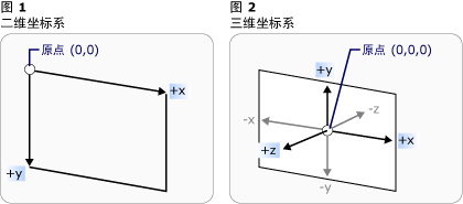
在3-D坐标系中,原点位于呈现区域的中心(即容器中心),x 轴上的正值朝右,但是 y 轴上的正值朝上,z 轴上的正值从原点向外朝向观察者。
照相机
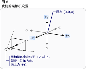
在接下来要介绍的示例中,我们用到的是PerspectiveCamera照相机。
PerspectiveCamera 指定3-D模型到2-D可视图面的投影。此投影包括透视缩短。 换言之,PerspectiveCamera描述各个面均聚集到某个水平点的平截体。对象离摄像机越近就显得越大,离得越远则显得越小。
立方体的创建
就此开始我们的示例。
3D场景
创建一个3D场景。
- <Window
- xmlns="http://schemas.microsoft.com/winfx/2006/xaml/presentation"
- xmlns:x="http://schemas.microsoft.com/winfx/2006/xaml"
- xmlns:d="http://schemas.microsoft.com/expression/blend/2008" xmlns:mc="http://schemas.openxmlformats.org/markup-compatibility/2006" mc:Ignorable="d" x:Class="WpfApplication1.MainWindow"
- Title="MainWindow" Height="350" Width="525">
- <Grid>
- <span style="color:#ff0000;"> <Viewport3D x:Name="Cube">
- </Viewport3D>
- </span> </Grid>
- </Window>
照相机
既然是3D场景,那当然得有观察的方向了,也就是照相机了。在3D场景中添加照相机。这里我们使用透视相机PerspectiveCamera 。
- <Grid>
- <Viewport3D>
- <span style="color:#ff0000;"> <Viewport3D.Camera>
- <PerspectiveCamera Position="0,0,8" x:Name="camera"></PerspectiveCamera>
- </Viewport3D.Camera>
- </Viewport3D>
- </Grid>
PerspectiveCamera 有很多属性,常用的有以下几个:
| Position | 获取或设置以世界坐标表示的摄像机位置。 (继承自ProjectionCamera。) |
| FieldOfView | 获取或设置一个值,该值表示摄像机的水平视角。 |
| LookDirection | 获取或设置定义摄像机在世界坐标中的拍摄方向的 Vector3D。(继承自 ProjectionCamera。) |
| NearPlaneDistance | 获取或设置一个值,该值指定到摄像机近端剪裁平面的摄像机的距离。(继承自ProjectionCamera。) |
| FarPlaneDistance | 获取或设置一个值,该值指定到摄像机远端剪裁平面的摄像机的距离。 (继承自ProjectionCamera。) |
| UpDirection | 获取或设置定义摄像机向上方向的 Vector3D。(继承自 ProjectionCamera。) |
我们现在从基本的做起,只定义了Position的属性。(0,0,8)意思为照相机距离屏幕为8.
模型
照相机也有了,现在就开始定义立方体模型了。大家都知道立方体有6个面,所以我们要定义6个GeometryModel3D。
- <Viewport3D>
- <Viewport3D.Camera>
- <PerspectiveCamera Position="0,0,8" x:Name="camera"></PerspectiveCamera>
- </Viewport3D.Camera>
- <Viewport3D.Children>
- <ModelVisual3D>
- <ModelVisual3D.Content>
- <Model3DGroup >
- <span style="color:#ff0000;"><GeometryModel3D>
- <GeometryModel3D.Material>
- <DiffuseMaterial Brush="Green"/>
- </GeometryModel3D.Material>
- <GeometryModel3D.Geometry>
- <MeshGeometry3D Positions="0,0,0 2,0,0 2,2,0 0,2,0"
- TriangleIndices="0,1,2 0,2,3">
- </MeshGeometry3D>
- </GeometryModel3D.Geometry>
- </GeometryModel3D>
- </span> </Model3DGroup>
- </ModelVisual3D.Content>
- </ModelVisual3D>
- </Viewport3D.Children>
- </Viewport3D>
Material是你要为模型填充的纹理,我们使用了绿色来填充。
MeshGeometry3D 用于生成3-D形状的三角形基元。这个说明太抽象,就是说你该定义你的模型框架了。
Positions="0,0,0 2,0,0 2,2,0 0,2,0" 定义了四个点。
有了这四个点,就应该开始绘制三角形基元,就是要把点串起来。TriangleIndices="0,1,2 0,2,3",意思是将0、1、2这三个顶点连起来组成一个三角形,将0、2、3这三个顶点连起来组成另一个三角。这里有一个技巧,我姑且这样理解,在建立三角形时,如果是逆时针连接顶点,那么建立的三角形就是面向视野的,如果是顺时针连接,就是背向视野的(向外),大家可以试一下TriangleIndices="0,3,2 0,2,1"。这样就绘制出如下图所示的一个面了。
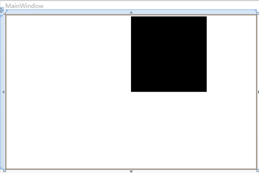
我们定义的是绿色,为什么是黑色的呢。天黑了,当然都是黑色的了!我们缺少光。
- <Viewport3D>
- <Viewport3D.Camera>
- <PerspectiveCamera Position="0,0,8" x:Name="camera"></PerspectiveCamera>
- </Viewport3D.Camera>
- <Viewport3D.Children>
- <ModelVisual3D>
- <ModelVisual3D.Content>
- <Model3DGroup >
- <GeometryModel3D>
- <GeometryModel3D.Material>
- <DiffuseMaterial Brush="Green"/>
- </GeometryModel3D.Material>
- <GeometryModel3D.Geometry>
- <MeshGeometry3D Positions="0,0,0 2,0,0 2,2,0 0,2,0"
- TriangleIndices="0,1,2 0,2,3">
- </MeshGeometry3D>
- </GeometryModel3D.Geometry>
- </GeometryModel3D>
- </Model3DGroup>
- </ModelVisual3D.Content>
- </ModelVisual3D>
- <span style="color:#ff0000;"> <ModelVisual3D x:Name="light">
- <ModelVisual3D.Content>
- <AmbientLight></AmbientLight>
- </ModelVisual3D.Content>
- </ModelVisual3D>
- </span> </Viewport3D.Children>
- </Viewport3D>
加上红色的那段代码,就有光了,有光了,就变绿了。
接下来给大家几种光,具体的大家可以自己试试。
-
AmbientLight:它所提供的环境光以一致的方式照亮所有的对象,而与对象的位置或方向无关。
-
DirectionalLight:像远处的光源那样照亮。 将方向光的 Direction 指定为 Vector3D,但是没有为方向光指定位置。
-
PointLight:像近处的光源那样照亮。 PointLight 具有一个位置并从该位置投射光。 场景中的对象是根据对象相对于光源的位置和距离而被照亮的。 PointLightBase 公开Range 属性,该属性确定一个距离,超过该距离后模型将无法由光源照亮。 PointLight 还公开了多个衰减属性,这些属性确定光源的亮度如何随距离的增加而减小。 您可以为光源的衰减指定恒定、线性或二次内插算法。
-
SpotLight:从 PointLight 继承。 Spotlight 的照亮方式与 PointLight 类似,但是它既具有位置又具有方向。 它们在 InnerConeAngle 和 OuterConeAngle 属性所设置的锥形区域(以度为单位指定)中投射光。
好了,至此已经做出来一个面了。那接下来重复上述动作,把其他五个面画全。
- <Grid >
- <Viewport3D Margin="10">
- <Viewport3D.Camera>
- <PerspectiveCamera Position="0,0,8" x:Name="camera"></PerspectiveCamera>
- </Viewport3D.Camera>
- <Viewport3D.Children>
- <ModelVisual3D>
- <ModelVisual3D.Content>
- <Model3DGroup >
- <GeometryModel3D x:Name="F1">
- <GeometryModel3D.Material>
- <DiffuseMaterial Brush="Green"/>
- </GeometryModel3D.Material>
- <GeometryModel3D.Geometry>
- <MeshGeometry3D Positions="0,0,0 2,0,0 2,2,0 0,2,0"
- ngleIndices="0,2,1 0,3,2">
- </MeshGeometry3D>
- </GeometryModel3D.Geometry>
- </GeometryModel3D>
- <GeometryModel3D x:Name="F2">
- <GeometryModel3D.Material>
- <DiffuseMaterial Brush="Blue"/>
- </GeometryModel3D.Material>
- <GeometryModel3D.Geometry>
- <MeshGeometry3D Positions="0,0,0 0,0,2 0,2,2 0,2,0"
- ngleIndices="0,1,2 0,2,3">
- </MeshGeometry3D>
- </GeometryModel3D.Geometry>
- </GeometryModel3D>
- <GeometryModel3D x:Name="F3">
- <GeometryModel3D.Material>
- <DiffuseMaterial Brush="Gray"/>
- </GeometryModel3D.Material>
- <GeometryModel3D.Geometry>
- <MeshGeometry3D Positions="0,0,0 0,0,2 2,0,2 2,0,0"
- ngleIndices="0,2,1 0,3,2">
- </MeshGeometry3D>
- </GeometryModel3D.Geometry>
- </GeometryModel3D>
- <GeometryModel3D x:Name="F4">
- <GeometryModel3D.Material>
- <DiffuseMaterial Brush="Bisque"/>
- </GeometryModel3D.Material>
- <GeometryModel3D.Geometry>
- <MeshGeometry3D Positions="2,0,0 2,2,0 2,2,2 2,0,2"
- ngleIndices="0,1,2 0,2,3">
- </MeshGeometry3D>
- </GeometryModel3D.Geometry>
- </GeometryModel3D>
- <GeometryModel3D x:Name="F5">
- <GeometryModel3D.Material>
- <DiffuseMaterial Brush="Yellow"/>
- </GeometryModel3D.Material>
- <GeometryModel3D.Geometry>
- <MeshGeometry3D Positions="0,2,2 2,2,2 2,2,0 0,2,0"
- ngleIndices="0,1,2 0,2,3">
- </MeshGeometry3D>
- </GeometryModel3D.Geometry>
- </GeometryModel3D>
- <GeometryModel3D x:Name="F6">
- <GeometryModel3D.Material>
- <DiffuseMaterial Brush="Red"/>
- </GeometryModel3D.Material>
- <GeometryModel3D.Geometry>
- <MeshGeometry3D Positions="0,2,2 2,2,2 0,0,2 2,0,2"
- ngleIndices="0,2,3 0,3,1">
- </MeshGeometry3D>
- </GeometryModel3D.Geometry>
- </GeometryModel3D>
- </Model3DGroup>
- </ModelVisual3D.Content>
- </ModelVisual3D>
- <ModelVisual3D x:Name="light">
- <ModelVisual3D.Content>
- <AmbientLight></AmbientLight>
- </ModelVisual3D.Content>
- </ModelVisual3D>
- </Viewport3D.Children>
- </Viewport3D>
- </Grid>
至此,立方体模型已经建立。大家可以用blend,来回转动试试!
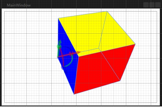
上面那个因为每个面的填充色不同,所以分为6个面来构造立方体。
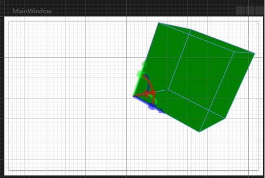
那么如果一个所有面都是绿色的立方体如何构建呢,还要那么麻烦吗。我们理解到Position代表顶点,一个立方体有8个顶点。那么从这8个顶点来构建立方体可以吗?
- <Grid >
- <Viewport3D Margin="10">
- <Viewport3D.Camera>
- <PerspectiveCamera Position="0,0,8" x:Name="camera"></PerspectiveCamera>
- </Viewport3D.Camera>
- <Viewport3D.Children>
- <ModelVisual3D>
- <ModelVisual3D.Content>
- <span style="color:#ff0000;"> <GeometryModel3D x:Name="F1">
- <GeometryModel3D.Material>
- <DiffuseMaterial Brush="Green"/>
- </GeometryModel3D.Material>
- <GeometryModel3D.Geometry>
- <MeshGeometry3D Positions="0,0,0 2,0,0 2,2,0 0,2,0 0,2,2 0,0,2 2,0,2 2,2,2"
- TriangleIndices="0,2,1 0,3,2 0,4,3 0,5,4 0,1,6 0,6,5 3,4,7 3,7,2 4,5,6 4,6,7 7,6,1 7,1,2">
- </MeshGeometry3D>
- </GeometryModel3D.Geometry>
- </GeometryModel3D>
- </span> </ModelVisual3D.Content>
- </ModelVisual3D>
- <ModelVisual3D x:Name="light">
- <ModelVisual3D.Content>
- <AmbientLight></AmbientLight>
- </ModelVisual3D.Content>
- </ModelVisual3D>
- </Viewport3D.Children>
- </Viewport3D>
- </Grid>
blend中查看图如下(经过变换的):
好了,立方体的构造到此结束。